Achieving true energy performance in building envelopes means going beyond labeled insulation R-values to understand what happens at every stud, header, and connection point. Thermal bridging through framing can reduce a wall's actual thermal performance by 20-30%, turning your carefully specified R-19 cavity insulation into something closer to R-15 in real-world conditions. Old Mill Building Products gives you the wall systems and detailing guidance to maximize whole-wall R-value while addressing moisture control and code compliance.
This guide walks you through everything you need to know about detailing CI wall systems—from fundamental building science principles to step-by-step installation sequences. You'll find spec-ready information on thermal bridge mitigation, moisture management strategies, and EIFS-compatible assemblies that help you achieve high-performance envelopes for both residential and commercial projects.
Key Takeaways: How to Detail Continuous Insulation Walls for R Value
- Exterior CI wraps the building in a thermal blanket, breaking the heat transfer pathway through wood and steel framing members.
- Proper CI detailing keeps sheathing warm enough to prevent moisture accumulation and condensation, improving wall durability significantly.
- Old Mill Building Products' Panel+ system integrates insulation, air barrier, and drainage in one code-compliant assembly with up to R-20 performance.
- Water control layer placement—either inside or outside the insulation—determines your window flashing approach and installation sequence.
- Whole-wall R-value calculations must account for framing fraction, and CI reduces the gap between nominal and effective thermal resistance.
What Is Whole-Wall R-Value and Why Does It Matter?
Whole-wall R-value represents the actual thermal performance of your entire wall assembly—not just the insulation between studs. It accounts for heat loss through framing members, headers, plates, and all other components that create thermal bridges.
According to the U.S. Department of Energy, the effectiveness of insulation depends heavily on how and where it's installed. Insulation compressed or bypassed by framing doesn't deliver its rated performance.
In a typical 16-inch on-center wall, approximately 25% of the wall area consists of solid wood framing. Since wood has an R-value of only about R-1.25 per inch, this creates significant pathways for heat to escape—even when cavity insulation performs perfectly.
How Do You Calculate Whole-Wall R-Value?
Calculating whole-wall R-value requires accounting for both cavity insulation and framing in parallel. Heat takes the path of least resistance, so you must combine thermal resistances using the parallel heat flow method.
The formula weighs the R-value of each component by its percentage of wall area. A wall with 75% cavity area at R-19 and 25% framing at R-5.5 (for a 2x6 stud) yields a whole-wall R-value closer to R-14.5—far below the labeled cavity insulation value.
CI changes this equation dramatically. Because exterior insulation covers 100% of the wall surface including framing, its full R-value adds directly to the whole-wall calculation.
How Does Exterior CI Reduce Thermal Bridging in Wall Systems?
Exterior CI breaks the thermal bridge by placing an uninterrupted insulation layer over the entire structural assembly. Heat can no longer conduct directly through studs and plates to the exterior environment.
Think of it as wrapping your building in a thermal blanket. The insulation layer sits outside the structural sheathing and behind the cladding, creating a thermal break between framing and outside air.
Research from Building Science Corporation confirms that exterior insulation on wall assemblies addresses many common building enclosure energy and durability issues. The thermal resistance benefits compound with cavity insulation for superior whole-wall performance.
What R-Value Thickness Do You Need for Different Climate Zones?
The required CI thickness depends on your climate zone, cavity insulation R-value, and moisture control strategy. Colder climates require more exterior insulation to keep sheathing above dew point temperatures.
The International Residential Code (IRC) Table R702.7(3) specifies minimum CI R-values by climate zone. For a 2x6 wall in Climate Zone 5, you'd need at least R-7.5 of exterior insulation. Climate Zone 7 requires R-10 or more.
These minimums exist for both thermal performance and moisture safety. Insufficient exterior insulation in cold climates can leave sheathing cold enough for condensation to form during winter months.
What Are Your Material Options for Exterior CI?
Several insulation materials work well as exterior CI, each with distinct characteristics affecting vapor permeability, fire rating, compressive strength, and installation requirements.
Rigid Foam Insulation: EPS, XPS, and Polyiso
Expanded polystyrene (EPS) offers R-3.5 to R-4.2 per inch with vapor permeability ranging from 2-5 perms per inch depending on density. EPS is cost-effective and available in multiple densities from Type I (lower compression resistance) to Type IX (higher compression resistance).
Extruded polystyrene (XPS) delivers R-5 per inch with lower vapor permeability around 0.5-1 perm per inch. While XPS resists moisture absorption better than EPS, its manufacturing process has higher global warming potential.
Polyisocyanurate (polyiso) achieves the highest R-value at R-5.7 to R-6.5 per inch. Foil-faced versions act as vapor retarders (Class I) and can serve as air barriers when seams are properly taped.
Mineral Wool Board Insulation
Mineral wool (rockwool) insulation boards offer approximately R-4 per inch with complete vapor openness. The material is hydrophobic, non-combustible, and an excellent choice for fire-rated assemblies or wildfire-prone areas.
Because mineral wool allows vapor to pass through, assemblies using it can dry both inward and outward. This flexibility simplifies moisture management in mixed climates.
Wood Fiber Insulation Boards
Wood fiber boards deliver R-3.5 per inch with moderate vapor permeability and excellent carbon credentials. Many products feature tongue-and-groove edges that simplify installation and reduce thermal bypasses at seams.
These boards can hold crisp cuts for architectural details and don't create the microplastic debris associated with foam products.
Where Should You Place the Water Control Layer?
Water control layer placement is one of the most critical decisions in CI wall design. You have two primary options: place the water-resistive barrier (WRB) behind the insulation at the sheathing plane, or place it in front of the insulation.
Either strategy works when detailed correctly. However, choosing one approach and applying it consistently across the entire project prevents flashing errors and reverse laps that lead to water intrusion.
WRB Behind the Insulation (Innie Windows)
Placing the WRB at the sheathing puts your primary moisture defense under the insulation layer. This works well with hydrophobic materials like mineral wool or XPS that won't be damaged by incidental moisture.
Windows install at the structural opening plane as "innie" configurations, with deep extension jambs reaching out to the cladding plane. Flashings integrate directly with the WRB at sheathing.
This approach requires careful attention to drainage. Use housewraps with drainage textures or install a dedicated drainage mat between foam and sheathing to prevent hydrostatic pressure from trapping water.
WRB in Front of the Insulation (Outie Windows)
Installing the WRB over the insulation allows traditional flanged window installation at the outer wall plane. Windows become "outies" set flush with the CI surface.
This strategy works especially well with hydrophilic insulations like paper-faced polyiso that could absorb water if exposed. The exterior WRB protects the insulation from bulk moisture.
Products like ThermalBuck extend the window mounting plane flush with the CI surface while maintaining the thermal break. This simplifies flashing details for crews familiar with standard installation methods.
How Do You Detail Window Openings in CI Wall Assemblies?
Window integration requires coordinating four control layers: water control, air control, vapor control, and thermal control. Each layer must connect to the window frame appropriately.
Step-by-Step Window Installation: Outie Configuration
First, tape sheathing seams continuously to the rough opening edges, establishing the air barrier at the structural plane. Roll all tape for proper adhesion.
Next, install the thermal buck product with elastomeric sealant. Tape the window frame to the buck with compatible acrylic tape, carrying air barrier continuity from sheathing to the window.
Install CI over the sheathing, cutting precisely around the window buck. Apply WRB over the insulation, cutting flush with buck edges on sides and creating upward-angled cuts at top corners.
Set the window with appropriately long screws through flanges into framing. Place shims under the bottom flange to create a drainage gap. Flash sides first, then top—never seal the bottom exterior.
Step-by-Step Window Installation: Innie Configuration
Build a plywood extension buck spanning from framing through sheathing to flush with the CI outer face. Wrap the buck with flashing tape lapping onto sheathing for water and air continuity.
Apply self-adhered membrane WRB to the entire wall, cutting around bucks and lapping over buck tape connections. This ties water and air control layers to the window opening.
Install flangeless windows with manufacturer-supplied clips or through predrilled holes directly into framing. Metal head flashing extends from the membrane over the buck and covers head casing.
How Do You Achieve Moisture Management in High R-Value Walls?
Moisture management in CI walls requires understanding vapor drive—the movement of water vapor from areas of higher concentration to lower concentration. In winter, vapor drives outward from heated interiors. In summer in hot-humid climates, it drives inward.
The goal is preventing vapor from accumulating at any surface cold enough for condensation while allowing assemblies to dry when they do get wet.
Understanding Vapor Permeability Classes
Materials are classified by vapor permeance: Class I vapor retarders permit less than 0.1 perms, Class II permits 0.1-1.0 perms, and Class III permits 1.0-10 perms. Materials above 10 perms are considered vapor open.
The thickness of your CI affects its permeance classification. XPS at 1 inch might rate 1.0 perms, but at 3 inches drops to 0.125 perms—effectively vapor closed.
A key building science principle: avoid double vapor barriers. If you install low-perm CI on the exterior, ensure the interior can dry inward. Vinyl wallpaper over low-perm foam creates an assembly that can't dry in either direction.
How CI Keeps Sheathing Warm and Dry
Exterior CI's most important durability benefit is keeping sheathing warm. When sheathing stays above dew point temperature, water vapor passing through the assembly doesn't condense on it.
The ratio of exterior to interior insulation matters significantly. Higher cavity R-values make sheathing colder because less heat reaches it. You must increase CI R-value proportionally to maintain sheathing temperature.
Old Mill Building Products' Panel+ system addresses this with integrated insulation delivering R-4.2 per inch. A 4-inch Panel+ installation achieves R-20 of exterior insulation, keeping sheathing warm even in extreme cold climate zones.
What Are Best Practices for Thermal Bridge Mitigation at Details?
Beyond field-of-wall CI, thermal bridging occurs at penetrations, connections, and transitions. Addressing these thermal bridges prevents energy loss and cold spots that cause condensation.
Foundation-to-Wall Transitions
The rim joist area creates a significant thermal bridge where framing meets the foundation. Extend CI below the sill plate line and install a kickout flashing at grade to protect the insulation bottom edge.
Interior spray foam at rim joists complements exterior CI but doesn't replace it. The combination creates a belt-and-suspenders approach to this vulnerable detail.
Roof-to-Wall Intersections
Where walls meet roof assemblies, CI must continue to the thermal boundary. This often means installing CI on walls before roofing to allow proper sequencing of control layer connections.
Plan this detail during framing. Trying to retrofit CI around existing roofing creates gaps and flashing complications that compromise both thermal and moisture performance.
Deck and Balcony Connections
Decks and balconies typically connect through the thermal envelope at ledger boards. Use thermal break products designed for this application, or design structural connections that don't penetrate the CI layer.
Cantilevered deck joists penetrating through CI create multiple thermal bridges. Each joist acts as a heat highway to the exterior.
How Do You Attach Cladding Over Exterior CI?
CI thickness affects cladding attachment strategy. At 1 inch or less, you can fasten directly through insulation to framing with appropriate-length nails. Beyond 1.5 inches, you need a secondary attachment plane.
Rainscreen Furring Strip Installation
Vertical furring strips (typically 3/4-inch by 1.5-inch or larger) installed over CI create a ventilated rainscreen cavity and a solid cladding attachment plane. Use structural screws long enough to penetrate framing by at least 1.5 inches.
For 2-inch CI, you'd need minimum 4-inch screws. At 4 inches of CI, screws extend to 6 inches or more. These longer fasteners require specialized guns or screw-driving techniques.
Compressive insulation like Type I EPS or mineral wool can deform under aggressive screw pressure. Higher-density foams (XPS, polyiso) resist crushing better. Consider reverse-thread screws that allow adjustment for coplanar furring alignment.
Cladding Weight and Fastener Spacing
Heavier claddings require closer furring spacing and more frequent screw connections. Fiber cement, stucco over lath, and adhered masonry veneer impose greater loads than wood or vinyl siding.
Consult manufacturer specifications or engineering tables for furring attachment schedules based on cladding weight, wind loads, and insulation thickness. The 2015 IRC includes prescriptive tables for common scenarios.
What Makes EIFS-Compatible Assemblies Different?
Exterior Insulation and Finish Systems (EIFS) integrate CI with finish coatings applied directly to the insulation surface. Modern drainage EIFS includes water management features that address historical moisture concerns.
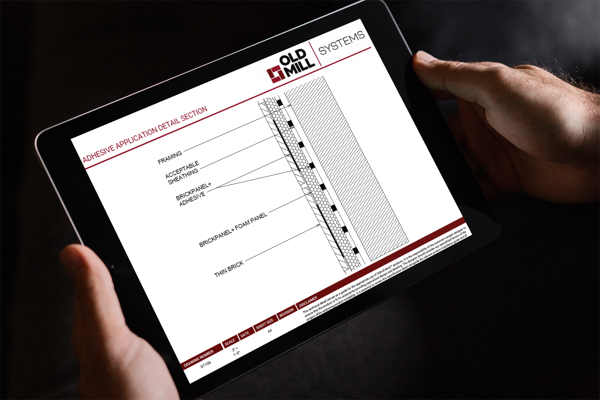
Drainage EIFS Components and Layers
Contemporary drainage EIFS assemblies include: substrate and sheathing, water-resistive barrier, adhesive attachment, insulation board (EPS or mineral wool), drainage plane with vertical channels, reinforcing mesh embedded in base coat, and finish coat.
The drainage plane between WRB and insulation—or between insulation and base coat—allows incidental moisture to exit through weep holes at the assembly base.
These systems achieve CI while creating a finished wall surface without additional cladding. The result is a cost-effective assembly meeting both energy codes and aesthetic requirements.
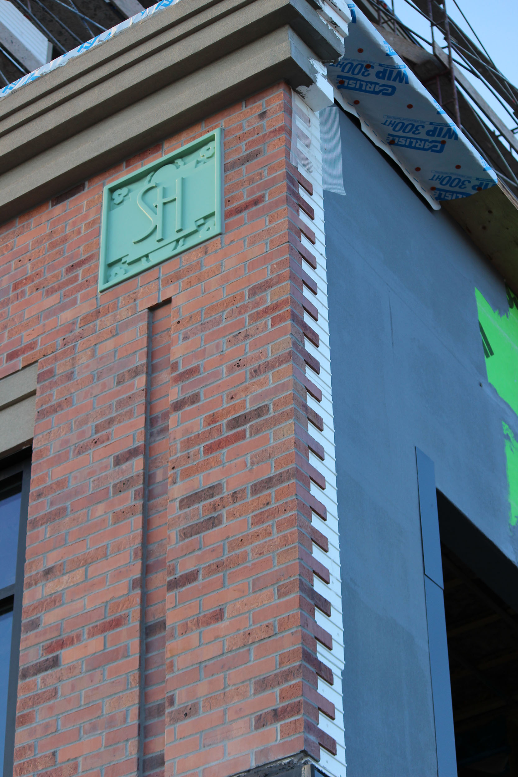
EIFS Assemblies with Thin Brick and Adhered Masonry Veneer
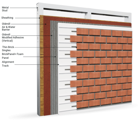
EIFS-compatible thin brick systems combine the thermal benefits of exterior insulation with the appearance and durability of genuine brick. The Old Mill Building Products Panel+ system works with thin brick, stone, and tile veneers.
Panel+ delivers integrated insulation with built-in drainage channels and air/water barrier compatibility. Combined with Brickwebb thin brick, you achieve a high-performance envelope with authentic brick aesthetics—without the weight and expense of full-thickness masonry.
The system meets NFPA 285 fire testing requirements for multi-story construction, addressing code compliance concerns that can limit insulated cladding options.
What Are Common Failure Modes in CI Wall Systems?
Understanding failure modes helps you avoid them during design and construction. Most problems stem from incorrect detailing rather than material failures.
Inconsistent Water Control Layer Location
The most common field error is mixing WRB locations—placing it behind insulation in some areas and in front in others. This creates reverse flashings and gaps where water enters but cannot exit.
Choose one WRB location strategy and apply it consistently. Document the decision clearly in specifications and pre-construction meetings.
Insufficient CI for Climate Zone
Using too little exterior insulation for your climate zone leads to cold sheathing and condensation risk. Follow IRC Table R702.7(3) minimums, and exceed them for higher-performance targets.
When in doubt, use more exterior insulation. The marginal cost of additional thickness is small compared to moisture damage remediation.
Poor Air Barrier Continuity
Air leakage through the envelope carries far more moisture than vapor diffusion. Gaps in air barriers at penetrations, transitions, and connections allow warm, humid air to contact cold surfaces where it condenses.
Tape, seal, and verify air barrier continuity at every joint and penetration. Blower door testing during construction identifies leaks while repair is still practical.
What QA Inspection Points Should You Include?
Build quality assurance into your CI wall construction with defined inspection points and acceptance criteria.
Pre-Installation Inspection Checklist
Before installing CI, verify: sheathing is properly installed and fastened, sheathing seams are taped for air barrier continuity where required, rough openings are properly sized and squared, and kickout flashings are installed at grade transitions.
Document substrate conditions with photos. Any issues discovered later become harder to address once buried under insulation.
During Installation Inspection Points
During CI installation, check: insulation boards are tight to sheathing without gaps, seams are staggered in multi-layer installations, tape adhesion is complete with no fish-mouths or lifted edges, and penetration flashings maintain WRB continuity.
Verify fastener patterns meet specifications. Under-fastened insulation can sag or separate over time.
Pre-Cladding Final Inspection
Before covering with cladding, confirm: all flashings are properly installed and lapped, window and door integration is complete, furring strips are coplanar and securely attached, and any incidental damage to insulation or WRB is repaired.
This inspection represents your last opportunity to correct issues before they're concealed. Take the time to do it thoroughly.
How Do Modern Energy Codes Address CI Requirements?
The International Energy Conservation Code (IECC) and ASHRAE 90.1 increasingly require CI in commercial and residential construction. Understanding code requirements helps you design compliant assemblies efficiently.
IECC Prescriptive Path Requirements
The IECC prescriptive path specifies minimum insulation R-values for wall assemblies by climate zone. Many zones allow a cavity-plus-CI approach (like R-13 + R-5 ci) as an alternative to high cavity insulation alone.
Climate Zone 4 and higher typically require either high cavity insulation values (R-20+) or moderate cavity with CI. The CI option often proves easier to achieve and more effective at reducing thermal bridging.
Performance Path Flexibility
Performance-based compliance allows trading thermal performance between envelope components. A high-performance wall with substantial CI can offset less insulation elsewhere—or support larger window areas.
Energy modeling demonstrates compliance by showing the proposed design meets or exceeds a code-compliant reference building's energy use. CI walls typically outperform reference buildings significantly.
In Conclusion: Building High R-Value Walls That Perform
Detailing CI wall systems for maximum R-value requires attention to thermal bridging, moisture management, and control layer continuity. The effort pays dividends in energy performance, durability, and occupant comfort throughout the building's life.
Start with building science fundamentals: keep sheathing warm, manage vapor drive, control bulk water, and maintain air barrier continuity. Choose CI materials appropriate for your climate, fire rating requirements, and construction methods.
Old Mill Building Products offers integrated wall systems like Panel+ that simplify high-performance envelope construction. With built-in insulation, drainage, and air barrier compatibility, these systems help you achieve code compliance and performance targets efficiently. Combined with thin brick or stone veneer, you deliver both energy performance and lasting aesthetics to your clients.
FAQs About How to Detail Continuous Insulation Walls for R Value
What is the minimum CI thickness for cold climate zones?
Cold climate zones (5-7) typically require R-7.5 to R-10 of exterior CI on 2x6 walls to keep sheathing warm enough to prevent condensation. Check IRC Table R702.7(3) for your specific climate zone requirements.
Old Mill Building Products' Panel+ system delivers R-4.2 per inch, so a 2-inch installation meets minimum requirements for Zone 5, while 3-inch panels satisfy Zone 7.
Can you use vapor-open CI in hot-humid climates?
Yes, vapor-open CI like mineral wool works in hot-humid climates when paired with appropriate interior vapor control. The assembly allows inward drying while the CI reduces cooling loads.
However, many hot-humid projects use low-perm CI intentionally to limit inward vapor drive. Both strategies work when detailed correctly for your specific conditions.
How do you flash windows in CI wall assemblies?
Window flashing depends on WRB location. With WRB behind CI, use extension bucks and flash to sheathing. With WRB over CI, flash directly to the membrane using standard techniques.
Products like ThermalBuck simplify flanged window installation over thick CI by extending the mounting plane while maintaining the thermal break.
Does CI eliminate the need for cavity insulation?
CI reduces but doesn't eliminate the value of cavity insulation. Combined approaches achieve higher whole-wall R-values than either strategy alone. The optimal ratio depends on climate zone and total R-value targets.
Old Mill Building Products recommends combining Panel+ CI with appropriate cavity insulation to maximize thermal performance while meeting code requirements.
What fasteners work best for attaching furring over thick CI?
Structural screws with aggressive threads designed for through-insulation attachment work well. Look for products specifically rated for cladding attachment over foam, with pull-out resistance values documented for various insulation thicknesses.
Fastener length must provide at least 1.5 inches of penetration into framing after passing through furring, CI, and sheathing. A 4-inch CI layer with 1-inch sheathing requires 6.5-inch minimum screws.
How does CI affect fire code compliance?
Foam plastic insulation must meet fire code requirements for the building type and location. NFPA 285 testing demonstrates fire performance for wall assemblies in buildings over 40 feet tall.
Old Mill Building Products' Panel+ system passes NFPA 285 testing, enabling its use in multi-story commercial and residential construction where fire codes would otherwise restrict foam insulation.