Specifying wall systems with exterior insulation and thin brick facades has become a critical skill for architects working on commercial and multifamily projects. Old Mill Building Products helps you navigate the complex intersection of energy codes, fire safety requirements, and moisture management—all while achieving the timeless aesthetic appeal of real clay brick.
This guide walks you through every step of the specification process, from understanding code requirements to selecting the right wall assembly components. By the end, you'll have a clear framework for confidently specifying code-compliant, high-performance wall systems that deliver lasting beauty and efficiency.
Key Takeaways: How to Specify CI Wall Systems for Thin Brick
- CI wall assemblies must integrate insulation, air/water barriers, and drainage to meet current IECC and ASHRAE 90.1 energy code requirements.
- NFPA 285 testing ensures your wall assembly prevents fire spread in noncombustible construction types I through IV above 40 feet.
- Old Mill Building Products offers Panel+ with NFPA 285 compliance and integrated moisture management for thin brick applications.
- Thermal bridging through studs can reduce effective R-values by up to 30%, making exterior CI essential for code compliance.
- Proper drainage plane design with weep details at flashing locations protects wall assemblies from moisture damage over time.
What Are CI Wall Systems and Why Do They Matter?
CI wall systems place insulation on the exterior side of structural framing, creating an unbroken thermal barrier around your building envelope. This approach differs from cavity insulation, where gaps at studs, plates, and headers create thermal bridges that significantly reduce overall wall performance.
According to research published by Fine Homebuilding, thermal bridging in typical 16-inch on-center framing can account for heat loss of up to 30% in insulated buildings. Placing insulation on the exterior side of the wall stops this energy loss by creating a thermal break at the sheathing plane.
Beyond energy efficiency, CI wall systems keep the sheathing warm enough to prevent moisture accumulation—the primary cause of mold, rot, and structural failure in wall assemblies. When vapor travels through wall materials and reaches a cold surface, condensation forms. By keeping the sheathing above dew point temperature, properly specified CI assemblies dramatically reduce this risk.
Understanding IECC Energy Code Requirements for Exterior Insulation
The International Energy Conservation Code (IECC) and ASHRAE 90.1 set minimum insulation requirements based on your project's climate zone. For commercial buildings, you'll need to meet prescriptive R-value requirements or demonstrate compliance through performance-based calculations.
Climate Zone Requirements for Commercial Wall Assemblies
In climate zones 4 through 8, the IECC requires CI for most above-grade wall assemblies in commercial construction. The specific R-value depends on your wall framing type (steel, wood, or mass wall) and the climate zone location.
For steel-framed walls, which have higher conductivity than wood, the code typically requires higher total R-values. Mass walls with brick or concrete backing can sometimes qualify for reduced insulation requirements due to their thermal mass properties.
How to Calculate Effective R-Value for Wall Assemblies
Your specified R-value only tells part of the story. The effective R-value accounts for thermal bridging through framing members, fasteners, and other penetrations. For accurate compliance documentation, use the parallel path calculation method described in ASHRAE 90.1 Appendix A.
With CI wall systems, you add the full R-value of exterior insulation to your assembly calculation—no derating required. A 2-inch EPS panel adds approximately R-8 to R-10, while mineral wool boards deliver around R-4 per inch. This additive approach makes hitting code targets more straightforward than relying solely on cavity insulation.
NFPA 285 Fire Testing Requirements for Thin Brick Wall Assemblies
NFPA 285 is an assembly test that evaluates how exterior wall systems with combustible components perform when exposed to a post-flashover interior fire. The International Building Code (IBC) requires NFPA 285 compliance for buildings of noncombustible construction types I through IV when walls contain combustible materials.
When Does Your Project Require NFPA 285 Compliance?
Your project needs NFPA 285 tested assemblies when the building exceeds 40 feet in height and the exterior wall contains combustible components. This includes foam plastic insulation (EPS, XPS, polyiso), air/water-resistive barriers with organic materials, and certain adhesives.
The test evaluates vertical and horizontal fire spread through the wall assembly. To pass, the assembly must prevent flames from propagating beyond specified limits both up the exterior face and between floor levels. Assemblies that pass can be used with confidence in noncombustible construction.
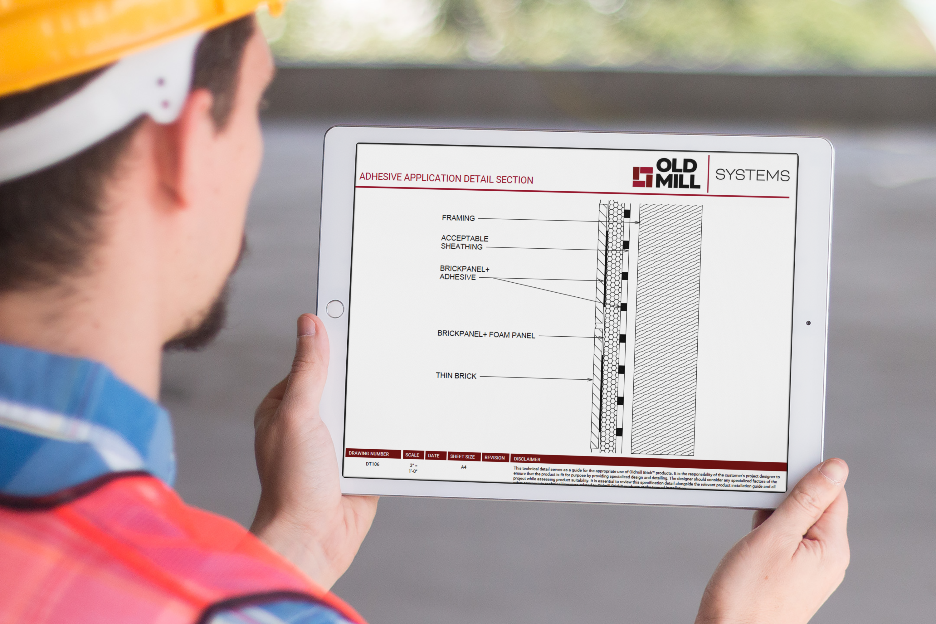
How Old Mill Building Products Addresses Fire Safety with Panel+
The Panel+ wall system from Old Mill Building Products delivers NFPA 285 compliance as part of an integrated assembly. Rather than cobbling together components from multiple manufacturers and hoping they've been tested in combination, you get a single-source system with documented fire performance.
Panel+ combines EPS foam insulation, integrated air/water barrier, and precision alignment for thin brick installation. The system has been tested and approved for use in noncombustible construction, giving you the specification documentation you need for permit approval.
Moisture Management Strategies for Thin Brick Facades
Water is every building's greatest threat. Your CI wall specification must include a clear strategy for managing bulk water, water vapor, and condensation. The three essential elements are: a water-resistive barrier (WRB), drainage plane, and proper flashing details.
Water-Resistive Barrier Placement Options
You can place your WRB either behind the insulation (at the sheathing plane) or in front of it (behind the cladding). Each approach has implications for window flashing, tie integration, and overall assembly performance.
For hydrophobic insulation materials like mineral wool or XPS, placing the WRB at the sheathing plane works well because water that gets past the insulation will drain down a textured WRB surface. For hydrophilic materials like paper-faced polyiso, placing the WRB outboard of the insulation keeps bulk water away from materials that could absorb and hold moisture.
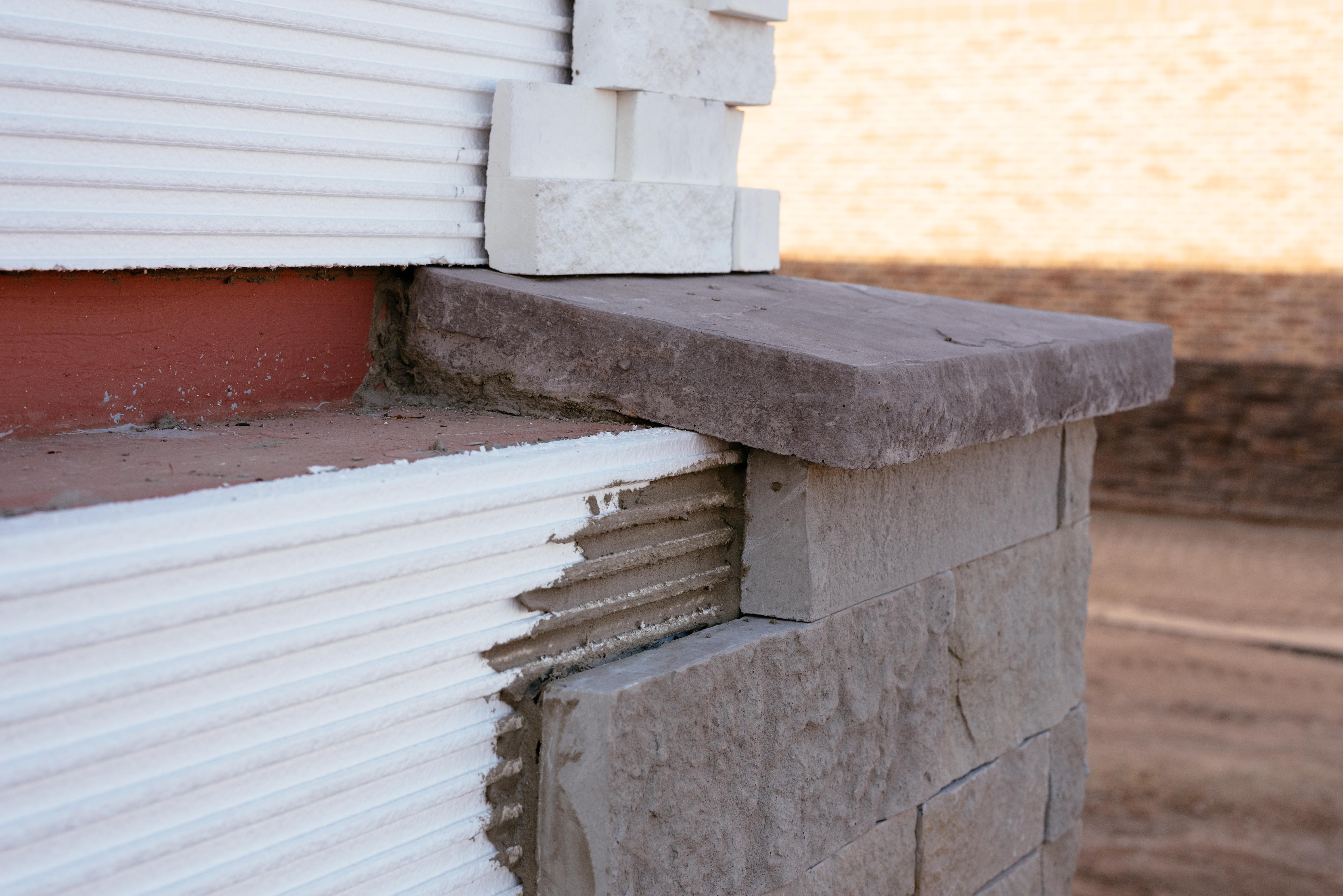
Drainage Plane Design and Weep Details
Every CI wall assembly needs a clear path for incidental water to exit the system. This requires vertical drainage channels and weeps at every point where moisture could accumulate—above windows, at floor lines, and at the base of the wall.
Old Mill Building Products engineered the Panel+ system with cross-drainage channels built into the panel profile. Water that enters the assembly moves both vertically and horizontally to reach weep locations, then exits through designed drainage points. This engineered approach eliminates guesswork and ensures consistent performance across the wall surface.
Selecting the Right Insulation Material for Your CI Assembly
Your choice of insulation material affects R-value, vapor permeability, compressive strength, fire resistance, and installation requirements. No single material excels at everything, so your selection should match project priorities.
Comparing EPS, XPS, Polyiso, and Mineral Wool
Expanded polystyrene (EPS) offers a balance of cost, performance, and environmental considerations. It doesn't require harmful blowing agents during production, has a vapor permeability that varies with density, and maintains stable R-value over time without thermal drift.
Extruded polystyrene (XPS) has higher compressive strength than EPS, making it a good choice for assemblies where fastener crush resistance matters. However, XPS has lower vapor permeability, which means walls with thick XPS layers must dry to the interior.
Polyisocyanurate (polyiso) delivers the highest R-value per inch—around R-5.6 to R-6—but foil-faced versions act as vapor retarders. Polyiso also experiences thermal drift, meaning its R-value decreases at very cold temperatures.
Mineral wool boards are non-combustible, hydrophobic, and vapor-open. They're an excellent choice in wildfire-prone areas where fire ratings take priority. The R-value is lower (around R-4 per inch), but the fire and moisture performance often justify the trade-off.
Matching Insulation Properties to Climate Zone Needs
In cold climates where vapor drives from inside to outside during heating season, you want the sheathing to stay warm enough to prevent condensation. The ratio of interior to exterior insulation matters here—if your cavity insulation has a higher R-value than your exterior CI, the sheathing gets colder and condensation risk increases.
In hot-humid climates, vapor drives from outside to inside during cooling season. Here, a less permeable exterior layer can reduce vapor diffusion into the conditioned space. Table R702.7(3) in the IRC gives minimum CI R-values by climate zone for residential construction; commercial projects should follow ASHRAE 90.1 requirements.
Step-by-Step Process for Specifying CI Wall Systems
A methodical approach to specification helps you catch coordination issues early and creates clear documentation for the construction team. Here's how to work through the key decisions.
Step 1: Define Performance Requirements
Start by listing every code requirement and project goal your wall assembly must meet. This includes IECC R-value targets, NFPA 285 compliance (if required), local fire zone ratings, acoustic performance, and any program requirements like LEED or Passive House.
Document the climate zone, building height, construction type, and occupancy classification. These factors determine which code sections apply and what testing documentation you'll need to submit for permit review.
Step 2: Select Your Wall Assembly Strategy
Choose between a component-based approach (specifying individual materials and trusting they work together) or a system-based approach (selecting a pre-engineered assembly with documented performance).
The system-based approach offers significant advantages for thin brick applications. Old Mill Building Products delivers an integrated solution with Panel+ that includes insulation, moisture management, and the alignment system for thin brick installation—all tested together for fire and moisture performance.
Step 3: Detail Window and Door Transitions
Window and door openings create the most challenging details in CI wall assemblies. You need to maintain air barrier continuity, flash water away from the opening, and create a stable mounting surface for the window frame.
For "outie" windows mounted at the CI plane, products like ThermalBuck extend the mounting surface while maintaining the thermal break. For "innie" windows set back into the wall, site-built plywood bucks wrapped with flashing tape connect all control layers to the window frame.
Step 4: Specify Control Layer Transitions
Your specifications must clearly identify every control layer and how it transitions at changes in assembly. At the foundation, specify how the air barrier connects to the concrete or foundation wall. At floor lines in multi-story buildings, detail how the CI continues past the floor diaphragm.
Where different cladding systems meet, show how the WRB integrates across the transition and where flashing prevents water from entering the assembly. Clear 3D details at these locations prevent field improvisation that can compromise system performance.
Window Integration Details for CI Walls with Thin Brick
Windows installed in CI walls require careful attention to flashing, air sealing, and structural support. The insulation layer creates a gap between the window frame and the structural rough opening that must be bridged properly.
Flashing Sequence for Outie Window Installation
For flanged windows mounted flush with the CI face, the flashing sequence follows standard practice with a few modifications. First, tape plywood seams all the way to the rough opening edges. Then install a thermal buck product, connecting it to the taped sheathing with acrylic tape for air barrier continuity.
After installing the WRB over the CI, cut it flush with the buck at the sides and pin back the top flap. Fasten the window through the flanges into the framing with appropriately long screws. Flash the sides first, then the head, leaving the sill unsealed to allow drainage.
Strategies for Innie Window Placement
Recessed windows set at the sheathing plane create deep reveals that offer aesthetic interest and sun shading. The installation uses a plywood buck sized to span from the framing face through the CI thickness.
Wrap the buck in self-adhered flashing membrane, lapping onto the sheathing plane. The CI fits around the buck, and a sloped rigid foam piece at the sill creates a drainage surface under the window. A metal sill pan completes the weatherproofing assembly.
Construction Administration Tips for CI Wall Assemblies
Even the most detailed specifications can fail if construction execution doesn't match design intent. Plan for field observation at critical milestones and create submittal requirements that verify material compliance before installation begins.
Submittal Requirements for CI Wall Components
Require manufacturer data sheets for every component showing R-value, vapor permeability, compressive strength, and fire test results. For NFPA 285 compliance, require the actual test report showing the tested assembly configuration—not just a letter claiming compliance.
If you specify a system like Panel+ from Old Mill Building Products, the submittal package includes coordinated documentation for all components. This single-source approach streamlines review and reduces the risk of incompatible material substitutions.
Field Observation Milestones
Schedule observations at WRB installation (before CI covers it), at window flashings (before trim covers them), and at base-of-wall details (before grade work conceals them). Document any deviations from the drawings and evaluate whether they affect performance.
Pay particular attention to penetrations. Every pipe, conduit, and anchor that passes through the wall creates a potential failure point for air, water, and thermal performance. Verify that sealants and flashings at penetrations match the specified products and installation methods.
Common Specification Mistakes to Avoid
Learning from others' errors saves time and prevents costly field corrections. Here are the most frequent issues encountered when specifying CI wall systems for thin brick.
Untested Material Combinations
NFPA 285 tests a specific assembly, not individual components. If you substitute a different insulation brand, WRB product, or adhesive than what was tested, you may invalidate the assembly's fire compliance. Always verify that your specified combination has documented test results.
Insufficient Fastener Embedment
CI creates thickness between the cladding attachment point and the structural framing. Your fasteners must penetrate through the rainscreen furring, CI, and sheathing, then embed into the framing by the code-required depth. For most siding attachment, that's 1½ inches into the stud. Do the math early—deep CI assemblies may require specialty fasteners.
Missing Drainage at Transitions
Water that enters the CI must be able to exit. Specify weeps at every horizontal interruption—window heads, shelf angles, ledges, and wall terminations. Without clear drainage paths, water accumulates and eventually causes damage.
Comparing CI Wall System Approaches for Commercial Projects
Several approaches to CI wall systems work with thin brick facades. Understanding the differences helps you select the right strategy for your project constraints.
EIFS with Thin Brick Finish
Exterior insulation and finish systems (EIFS) apply CI directly to sheathing, followed by a base coat, reinforcing mesh, and finish. For thin brick, the finish layer becomes an adhesive bed that receives the brick veneer. Modern drainable EIFS includes a secondary moisture barrier and vertical drainage channels.
EIFS can achieve high R-values at relatively low cost, but the brick attachment relies on adhesive bond alone. Impact resistance depends on the mesh reinforcement and base coat thickness.
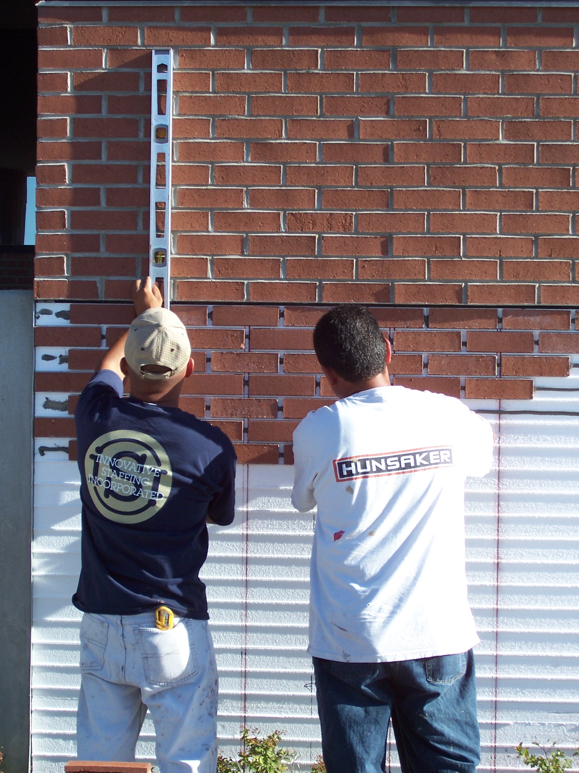
Panelized CI Systems
Panelized systems attach thin brick to insulated backing panels in a controlled factory environment, then ship complete panels to the job site. This approach improves quality control and speeds installation, making it popular for tight construction schedules.
Panel+ from Old Mill Building Products represents this category, integrating insulation, moisture management, and a precision alignment system for thin brick installation. The factory-controlled process ensures consistent panel quality, and field installation focuses on panel-to-panel joints rather than individual component assembly.
Mechanically Attached Thin Brick on CI
Some systems use mechanical fasteners or track systems to secure thin brick over CI. This approach offers positive attachment that doesn't rely solely on adhesive bond. The mechanical components must be evaluated for thermal bridging impact and integrated with the moisture management strategy.
Achieving Energy Goals Beyond Code Minimum
Meeting code is the starting point, not the finish line. Many projects target energy performance well beyond IECC minimums for cost savings, environmental certification, or owner preference.
How Much Insulation Do You Really Need?
Energy modeling helps quantify the return on investment for increased insulation. Beyond a certain thickness, adding more CI yields diminishing returns. The optimal point depends on energy costs, climate severity, and building occupancy patterns.
For passive house certification, you'll likely need R-40 or higher total wall assemblies. This typically means 4 to 6 inches of exterior CI combined with insulated framing cavities. At these thicknesses, fastener selection and structural attachment details become increasingly important.
Accounting for Thermal Bridging at Structural Connections
Even with CI, some thermal bridging occurs at cladding attachment points and structural shelf angles. Thermal modeling software can quantify these point losses and help you evaluate mitigation strategies like thermal break clips or insulated shelf angle brackets.
The goal is to minimize these bridges while maintaining structural integrity. Products designed specifically for CI walls often include features that reduce thermal conductivity at connection points.
Conclusion: Specifying CI Wall Systems That Deliver Long-Term Performance
Successful CI wall specifications start with clear performance requirements and work systematically through material selection, detailing, and construction documentation. By addressing code compliance, fire safety, moisture management, and energy performance as an integrated whole, you create wall assemblies that protect buildings for decades.
Old Mill Building Products simplifies this process with the Panel+ system—an integrated solution that combines insulation, moisture management, and thin brick installation into a single specification. The NFPA 285 compliant assembly, backed by a 15-year warranty, gives you confidence that your specified wall will perform as intended.
Take time to understand the underlying building science principles, document your control layers clearly, and verify field execution at critical milestones. The result will be thin brick facades that deliver beauty, durability, and efficiency for the life of the building.
FAQs About How to Specify CI Wall Systems for Thin Brick
What R-value do I need for CI in my climate zone?
R-value requirements vary by climate zone, wall type, and building occupancy. ASHRAE 90.1 and IECC tables specify minimums ranging from R-5 in warmer zones to R-25 or higher in cold climates.
For commercial steel-framed walls in climate zones 5 through 8, expect requirements around R-15 to R-25. Always verify current code requirements for your specific jurisdiction.
Does NFPA 285 apply to all buildings with thin brick and CI?
NFPA 285 applies to buildings of noncombustible construction types I through IV when walls exceed 40 feet in height and contain combustible components. Most foam plastic insulations and air/water barriers trigger this requirement.
For shorter buildings or combustible construction types V and III-B, other fire provisions apply but NFPA 285 may not be required. Consult your local authority having jurisdiction for specific applicability.
How does Old Mill Building Products address NFPA 285 requirements?
Old Mill Building Products offers the Panel+ system with documented NFPA 285 compliance as a tested assembly. This means you can specify Panel+ with confidence that all components have been evaluated together for fire propagation resistance.
The single-source approach eliminates the risk of untested component substitutions that could void fire compliance.
What thickness of CI is typical for thin brick wall assemblies?
Most thin brick CI assemblies use 1.5 to 4 inches of insulation, depending on climate zone and performance targets. Panel+ from Old Mill Building Products comes in thickness options from 1 inch to 4 inches, plus custom configurations for higher R-value requirements.
Thicker CI requires longer fasteners and may affect window buck depths, so factor these implications into your early design decisions.
Can I mix insulation types in a CI wall assembly?
You can use multiple insulation layers with different materials, but you must verify that the complete assembly has been tested for NFPA 285 if required. Each layer's vapor permeability also affects moisture flow through the assembly.
Calculate overall vapor resistance to confirm the assembly can dry in at least one direction. Avoid creating a "double vapor barrier" where moisture becomes trapped with no drying path.
How do I detail weeps in a CI thin brick wall?
Install weeps immediately above every through-wall flashing location, including base of wall, window heads, shelf angles, and ledges. Open head joint weeps at 24 inches on center work well for thin brick, with mesh or screens to exclude insects.
Old Mill Building Products designs Panel+ with built-in drainage channels that direct water to weep locations, ensuring moisture exits the assembly rather than accumulating behind the brick.